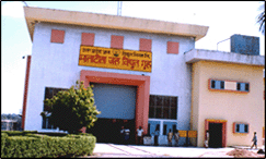
Hydro Electric Project, Matatila
Installed capacity - 3 x 10.2=30.6MW
No. of units - 3
Matatila Power Station is located in Lalitpur district (UP), 60 K.m. far from Jhansi City. Nearest Railway Station is Jhansi on Delhi Bombay route.
Power Station is situated at left bank of river Betwa which rises from Bhopal in the Vindhyan Plateau at an elevation of 1550ft, passes through granite rocks at a sleep gradient, the river flows on outskirts of distt. Jhansi forming boundary line of U.P. and M. P and thereafter it mostly flows in U.P., meeting the river Yamuna in Hamirpur Distt in U.P.It is entirely a rain fed river with very high discharge of water during rainy season and extremely low discharge during summers. The dam was constructed in year 1957 for irrigation purpose. Matatila power House with three machines of 10.2 MW each on the existing Dam has been commissioned in 1965.
Catchment Area - 8000 Sq. Miles.
Reservoir Capacity at - 40000 M. Cu. Ft.
Full level (R L 1012ft)
The Climate of Matatila dam is very hot in summer season and some time temperature rises upto 50ºC during summer and very cold during winter season. There is monsoon rains in summer season only The climate is dry in rest of the year.
Masonary dam flanked by earthen embankments on either side.
|
||||||||||||||||||||||||||||||||
|
||||||||||||||||||||||||||||||||
Penstock |
||||||||||||||||||||||||||||||||
|
||||||||||||||||||||||||||||||||
Building |
||||||||||||||||||||||||||||||||
|
Power station building is located at left bank of the Dm, Length of the building is 205 meters, Width - 76.5 meters, Height - 109 meters, Control room of power house is located at left side of the building.
Above mentioned boards are installed in control room. |
||||||||||||||||||||||||||||||||
|
||||||||||||||||||||||||||||||||
Turbine |
||||||||||||||||||||||||||||||||
|
||||||||||||||||||||||||||||||||
|
||||||||||||||||||||||||||||||||
Type of Generator & Excitation System |
||||||||||||||||||||||||||||||||
|
||||||||||||||||||||||||||||||||
|
||||||||||||||||||||||||||||||||
Details of The Tailrace |
||||||||||||||||||||||||||||||||
|
||||||||||||||||||||||||||||||||
Firm Power and Annual Energy Generation |
||||||||||||||||||||||||||||||||
|
||||||||||||||||||||||||||||||||
Details of Switch Yard |
||||||||||||||||||||||||||||||||
|
||||||||||||||||||||||||||||||||
|
||||||||||||||||||||||||||||||||
|
||||||||||||||||||||||||||||||||
Total Project Cost / Cost of Generation |
||||||||||||||||||||||||||||||||
|
(1). (a) Net cost of Generation (F.Y. 2000-01)
- 17.28 Paise per Unit (b) Total Project cost - 416.009 Lacs |
||||||||||||||||||||||||||||||||
| (2). Unit wise details of the machines as per name plate for both turbine and Generator:- | ||||||||||||||||||||||||||||||||
|
ACTUATOR GENERATOR
For 12000 KVA Actuator RPM --250 MFG. No.-- 106464 Date-- 1963 |
||||||||||||||||||||||||||||||||
DC Generator |
||||||||||||||||||||||||||||||||
|
||||||||||||||||||||||||||||||||
Alternating Current Generator |
||||||||||||||||||||||||||||||||
|
||||||||||||||||||||||||||||||||
Water Turbine |
||||||||||||||||||||||||||||||||
|
||||||||||||||||||||||||||||||||
| (5). General information in respect of Generation from the units and auxiliary consumption. | ||||||||||||||||||||||||||||||||
|
(a) Details of annual generation of last 6 years.
|
||||||||||||||||||||||||||||||||
|
1996-97 - 131.172 MU
1997-98 - 157.997 MU 1998-99 - 132.805 MU 1999-00 - 160.909 MU 2000-01 - 138.083 MU 2001-02 - 140.203 MU |
||||||||||||||||||||||||||||||||
|
(b) Auxiliary consumption of the plant is approximately 0.2% of Generation.
|
||||||||||||||||||||||||||||||||
| (6). Schedule for annual maintenance | ||||||||||||||||||||||||||||||||
|
Annual maintenance of one M/C of Matatila Power House is being done each year for
smooth Running of M/c's as per instructions issued earlier.
|
||||||||||||||||||||||||||||||||
| (7). R.L.A & L.E. of Matatila Power House is proposed to be carried out by M/S BHEL and order for the same has already been placed. | ||||||||||||||||||||||||||||||||
| (8). An E.O.T crane of 80 ton capacity has already been installed in Power House for dismantaling and erection Works. A mechanical workshop having lathe M/C, Shapers, drill M/C & Welding M/C has also been installed in Matatila Power House. | ||||||||||||||||||||||||||||||||
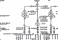
| Single Line Diagrame of Matatila Power House | ||||||||||||||||||||||||||||||||

|
||||||||||||||||||||||||||||||||